OPC UA
This manual describes how to connect to an OPC UA server that uses the OPC UA protocol.
The driver acts as an OPC UA Client and supports data transfer using OPC UA – Data Access with simple data types.
Arrays, structures or Data Unit Types are not supported.
The following OPC AU servers have been tested, with good result, but any OPC UA server fulfilling the standard is expected to work:
• B&R controllers configured to act as OPC UA servers.
• Beckhoff controllers using the TwinCAT OPC UA Server.
• Beijer Electronics iX operator panels and applications.
• Schneider controllers using the EcoStruxure OPC UA Server.
For information about the OPC UA server we refer to the manual for the OPC UA server.
Connecting to the server
Connection in a network is made according to Ethernet standards. To extend the network a hub or switch may be used.
Connection with controllers and communication modules
In order to be able to communicate with the OPC UA server additional settings must be set up in the server settings.
For further information about how to set up the OPC UA server and information on how to use the server to the manuals for those systems.
A basic example of how to set up communications with an OPC UA server, can be found in Appendix A.
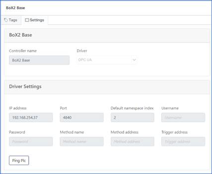
Driver settings
This section describes all the available setting in the driver, and what they do:
Ip Address – This is the IP-address of the OPC UA Server this is set in the system that runs the OPC UA Server.
Port – This is the TCP port used for communication, the default standard port is 4840. Change this to match the settings in the OPC UA Server.
Default namespace index – The OPC UA server TagProvider namespace, this differs between different server implementations. This is usually 2 for iX-application and 6 for B&R controllers.
Username – This is the username used for logging in to the OPC UA server. In applications with no authentication, leave this field empty.
Password – This is the password used for logging in to the OPC UA server. In applications with no authentication, leave this field empty.
The following fields are optional and only relevant if the OPC UA Server supports methods. Method name – This is the name of the OPC UA server method to be triggered using the tag in the Trigger address field.
Method address – This is the address of the OPC UA server method to be triggered using the tag in the Trigger address field.
Trigger address – This is the tag name of the tag in tag list that triggers the method action. A transition from zero to a non-zero value will trigger the method.
Addressing
The OPC UA protocol uses symbolic notation, meaning that signals are given human readable string-based names. Most OPC UA servers allow users to browse and add signals directly from the OPC UA Server namespace. If this option is not available, it is possible to import tag lists in the form of an Excel spread sheet.
Supported data types
The OPC UA Client only supports, simple data types. Arrays, structures or Data Unit Types are not supported. The driver had been tested and supports the following data types.
Digital signals
Bool – Single bit status, True or False
Analog signals
Byte – 8 bit, unsigned integer value 0 – 255.
Int16 – 16 bit integer value, with sign -32768 – 32767.
UInt16 – 16 bit integer value 0 – 65535.
Int32 – 32 bit integer value, with sign -2147483648 - 2147483647.
UInt32 – 32 bit integer value 0 - 42949672967.
Real – Float - 32 bit IEEE 754 single-precision floating point value.
LReal – Double - 64 bit IEEE 754 double -precision floating point value.
Misc. signals
String – a sequential collection of unicode characters that is used to represent text.
DateTime – represents an instant in time, typically expressed as a date and time of day.
Appendix A.
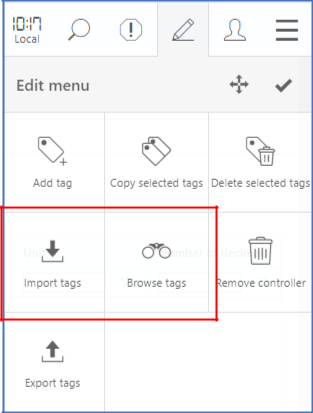
This appendix contains a basic example of how to add tags to the tag list using the Browse tags feature in the portal.
Fetching values from an OPC UA server
Driver settings in the portal
Make sure that the IP address matches the IP address of the OPC Server and that the configuration is sent to the gateway.
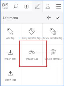
Browse tags.
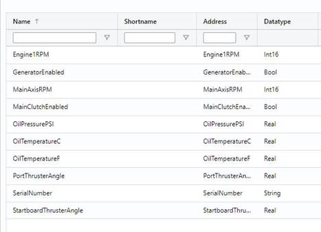
Select tags to add.
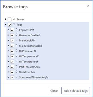
The selected tags are fetched together with additional information and added to the tag list.
Disclaimer
Please note that changes in the server setup or hardware, which may interfere with the functionality of this driver, may have occurred since this documentation was created. It is therefore important that you always test and verify the functionality of the application. To accommodate developments in the server setup and hardware, drivers are continuously updated. Accordingly, always ensure that the latest driver is used in the application.