Introduction
This manual describes how to connect to a Mitsubishi MELSEC controller that uses the MC Protocol. The driver supports binary 3E-framing only. Examples of units that can use the MC Protocol / SLMP (Seamless Message Protocol) are: E71-based modules on QnA and Qnn systems, for example the QJ71E71-T100 module QnUDE(H) – CPUs with built-in ethernet connection.
FX5U- Compact controllers with built-in ethernet connection
For information about the controller we refer to the manual for the current system.
Connecting to the Controller
Connection in a network is made according to Ethernet standards. To extend the network a hub or switch may be used.
Communication data code
The MC Protocol driver only supports the binary code communication data code mode.
Connection with controllers and communication modules
In order to be able to communicate with the controller CPU or a communication module, additional settings must be set up, using the controller programming software.
For further information about how to set up the controller or the communication module, cable specifications and information on how to use the controller or the communication module we refer to the manuals for those devices. A basic example of how to set up a FX5U controller, can be found in Appendix A.
Driver Settings
Ip Address – This is the IP-address that the PLC/communication module is set use in the PLC programming software.
Port – This is the TCP or UDP that the PLC/communication module is set use in the PLC programming software.
Note that some older programming environments display the port setting as a hexadecimal number. This port number should be a decimal integer between 1 and 65535.
Communication mode – TCP/IP or UDP/IP communication mode that the PLC/communication module is set use in the PLC programming software.
CPU – The CPU slot the driver will communicate with. If you only have one CPU or, leave this setting
to the default value “ControlPLC”. Otherwise select which CPU that shall be addressed.
X/Y Addressing - Select if hexadecimal or octal addressing shall be used for addressing inputs and outputs (X/Y). Larger systems(A/Q/L/R) typically uses hexadecimal addressing, FX5U used octal addressing.
Addressing
The following signal types are available and implemented in the driver.
Digital Signals
| X | Input Relay, hexadecimal addressing/octal addressing. | Ex. X1A / X5 |
|---|---|---|
| Y | Output Relay, hexadecimal addressing/octal addressing. | Ex. XA / X7 |
| M | Internal Relay, decimal addressing. | Ex. M314 |
| SM | Special Internal Relay, decimal addressing. | Ex. SM42 |
| B | Link Relay, hexadecimal addressing. | Ex. B2C |
| SB | Link Special Relay, decimal addressing. | Ex. SB16 |
| L | Latch Relay, decimal addressing. | Ex. L14 |
| F | Error Relay, decimal addressing. | Ex. F3 |
| V | Edge Relay, decimal addressing. | Ex. V2 |
| TS | Timer Contact, decimal addressing. | Ex. TS19 |
| CS | Counter Contact, decimal addressing. | Ex. CS9 |
| TC | Timer Coil, decimal addressing. | Ex. TC9 |
Analog Signals
| T/TN | Timer, decimal addressing. | Ex. T19 / TN19 |
|---|---|---|
| ST | Accumulated Timer, decimal addressing. | Ex. S8 |
| C/CN | Counter, decimal addressing. | Ex. C9 / CN9 |
| D | Data Register, decimal addressing. | Ex. D16 |
| Z | Index Register, decimal addressing. | Ex. Z23 |
| W | Link Register, hexadecimal addressing. | Ex. W2D |
| SW | Link Special Register, hexadecimal addressing. | Ex. SW1C |
| R | File Register, decimal addressing - Read only. | Ex. R18 |
| ZR | File Register for addressing one flow, dec. addr. - Read only. | Ex. ZR7 |
Supported Data Types
The driver had been tested and supports the following data types
Digital signals
Bool – Single bit status, True or False
Analog signals
Int16 – 16 bit, single register value, with sign. UInt16 – 16 bit, single register value, unsigned. Int32 – 32 bit, two consecutive 16-bit registers, register value, with sign. UInt32 – 32 bit, two consecutive 16-bit registers, unsigned. Float/Real - 32 bit, two consecutive 16-bit registers, with floating point.
Appendix A.
In this section you can find one example that shows how to set up ethernet communication on a device, for a more detailed description we refer to the manual for the system at hand. Setting the IP-address and netmask on a FX5U in GX Developer 3
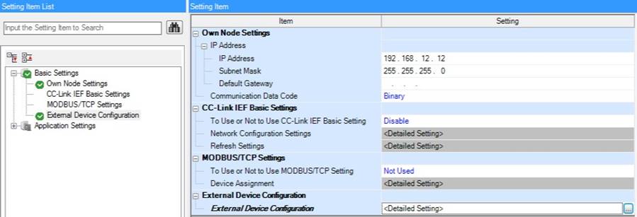
In the example above, the Mitsubishi FX5U is set to use IP-address 192.16.12.12 with a netmask of 255.255.255.0.
Important to note is that the Communication Data Code must be set to Binary for the driver to be able to fetch and write data from and to the Controller.
Setting communication channels on a FX5U in GX Developer 3
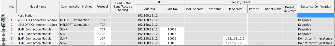
With the settings above the controller will have a total of four communication channels (3-6) that can be used to communicate using the Mitsubishi MC protocol driver in several different communication modes, called SLMP in the screenshot above.
Disclaimer
Please note that changes in the controller protocol or hardware, which may interfere with the functionality of this driver, may have occurred since this documentation was created. It is therefore important that you always test and verify the functionality of the application. To accommodate developments in the controller protocol and hardware, drivers are continuously updated. Accordingly, always ensure that the latest driver is used in the application.