Siemens S7
This manual describes how to connect the Siemens SIMATIC S7 controllers to the driver, and how they communicate via ISO over TCP/IP.
Addressing of an item in the controller is made in the regular SIMATIC notation, more about addressing can be found in the Addressing section of this document.
The driver supports the SIMATIC S7 200, 300, 400, 1200 and 1500 series controllers.
For information about the controller we refer to the manual for the current system.
Connecting to the controller
Connection in a network is made according to Ethernet standards.
To extend the network a hub or switch may be used.
Firmware considerations
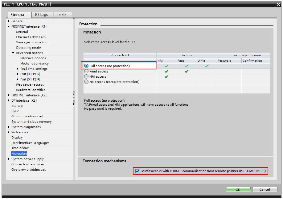
Note: Some controller firmware revisions have an increased security level which means that some settings need to be changed before a connection can be made. In the TIA software these settings are available under Device configuration -> Protection. Make sure to set the "Permit access with PUT/GET communication..." checkbox.
Connection with controllers and communication modules
In order to be able to communicate with the controller CPU or a communication module, additional settings must be set up, using the controller programming software.
For further information about how to set up the controller or the communication module, cable specifications and information on how to use the controller or the communication module we refer to the manuals for those devices. A basic example of how to map tags to signals in a data block, can be found in Appendix A.
Driver settings
This section describes all the available setting in the driver, and what they do
IP Address – This is the IP-address that the PLC/communication module.
Port – This is the TCP port that the PLC/communication module uses.
The default port number is usually 102. This should be a decimal 1 - 65535.
Slot – The slot number used for communication. This should be a decimal integer 1 - 31.
The default rack number for S7 -300/ -400/-1200 and -1500, is usually 2 (two).
Rack– The rack number used for communication. This should be a decimal integer 0 - 7.
The default rack number for S7 -300/ -400/-1200 and -1500, is usually 0 (zero).
Addressing
The following signal types are available and implemented in the driver.
Digital signals
| x – decimal address, integer 0 - 65535. b – decimal bit-offset, integer 0 - 7 | n – datablock | ||
|---|---|---|---|
| DBn.DBXx.b | Single bit from datablock n, address x bit b. | Ex. DB1.DBX0.3 | |
| Ix.b | Discrete input, read from address x bit b. | (IEC not.) | Ex. I17.4 |
| Ex.b | Discrete input, read from address x bit b. | (Siematic not.) | Ex. E17.6 |
| Qx.b | Discrete output, write to address x bit b. | (IEC not.) | Ex. Q23.4 |
| Ax.b | Discrete output, write to address x bit b. | (Siematic not.) | Ex. A23.2 |
| Mx.b | Discrete internal memory, address x bit b. | Ex. M47.3 |
Analog signals
| DBn.DBWx | Word from datablock n, address x bit b. | Ex. DB1.DBW24 | |
|---|---|---|---|
| DBn.DBDx | DWord from datablock n, address x bit b. | Ex. DB1.DBD18 | |
| IBx | Byte input read from address x. | (IEC not.) | Ex. IB17 |
| IWx | Word input read from address x. | (IEC not.) | Ex. IW17 |
| IDx | DWord input read from address x. | (IEC not.) | Ex. ID17 |
| EBx | Byte input read from address x. | (Siematic not.) | Ex. EB17 |
| EWx | Word input read from address x. | (Siematic not.) | Ex. EW17 |
| EDx | DWord input read from address x. | (Siematic not.) | Ex. ED17 |
| QBx | Byte output, write to address x. | (IEC not.) | Ex. QB23 |
| QWx | Word output, write to address x. | (IEC not.) | Ex. QW23 |
| QDx | DWord output, write to address x. | (IEC not.) | Ex. QD23 |
| ABx | Byte output, write to address x. | (Siematic not.) | Ex. AB23 |
| AWx | Word output, write to address x. | (Siematic not.) | Ex. AW23 |
| ADx | DWord output, write to address x. | (Siematic not.) | Ex. AD23 |
Analog signals continued
| MBx | Byte internal memory, address x. | Ex. MB47 | |
|---|---|---|---|
| MWx | Word internal memory, address x. | Ex. MW47 | |
| MDx | DWord internal memory, address x. | Ex. MD47 | |
| AIx | Word Analog Input, address x. | (IEC not.) | Ex. AI5 |
| AEx | Word Analog Input, address x. | (Siematic not.) | Ex. AE5 |
| AIWx | Word Analog Input, address x. | (IEC not.) | Ex. AIW5 |
| AEWx | Word Analog Input, address x. | (Siematic not.) | Ex. AEW5 |
| AQx | Word Analog Output, address x. | (IEC not.) | Ex. AQ5 |
| AAx | Word Analog Output, address x. | (Siematic not.) | Ex. AA5 |
| AQWx | Word Analog Output, address x. | (IEC not.) | Ex. AQW5 |
| AAWx | Word Analog Output, address x. | (Siematic not.) | Ex. AAW5 |
Supported data types
The driver had been tested and supports the following data types
Digital signals
Bool – Single bit status, True or False
Analog signals
Int16 – 16 bit (two bytes), single register value, with sign.
UInt16 – 16 bit (two bytes), single register value, unsigned.
Int32 – 32 bit (four bytes), two consecutive 16-bit registers, register value, with sign.
UInt32 – 32 bit (four bytes), two consecutive 16-bit registers, unsigned.
Float/Real - 32 bit (four bytes), two consecutive 16-bit registers, with floating point.
Appendix A.
In this appendix you can find examples on how to set up tags in driver to match registers and signals in the Siematic controller programming software.
With the following signals, set up in Data block 1 (screen dump from the TIA-portal):
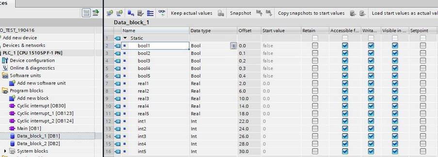
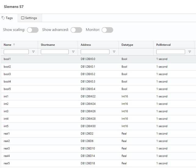
The matching tag list looks like this:
Disclaimer
Please note that changes in the controller protocol or hardware, which may interfere with the functionality of this driver, may have occurred since this documentation was created.
It is therefore important that you always test and verify the functionality of the application.
To accommodate developments in the controller protocol and hardware, drivers are continuously updated.
Accordingly, always ensure that the latest driver is used in the application.