Modbus
This manual describes how to connect to a Modbus TCP Slave device using the Modbus Master TCP driver.
Connecting to the controller
Connection in a network is made according to Ethernet standards. To extend the network a hub or switch may be used.
Connection with controllers and communication modules
In order to be able to communicate with the controller CPU or a communication module, additional settings might have to be set up, using the controller programming software or other configuration software. For further information about how to set up the device, cable specifications and information on how to use the device we refer to the manuals for those devices
Driver settings
Address – This is the IP-address of the Modbus TCP Slave.
Port – The TCP port of the Modbus TCP Slave. The default port is 502, this is rarely changed.
Slave address – If no slave address field, this slave address is used, this is rarely changed.
Endian – Little Endian (Motorola) or Big Endian(Intel), defines how high byte and low byte are
arranged for 16-bit registers. Big-endian have most significant byte first while little-endian have least
significant byte first.
Address Base – With address base zero, the first coil, input, input register and holding register is coil,
input, input register and holding register zero. With address base one, the first coil, input, input
register and holding register is coil, input, input register and holding register one.
Word Swapped – When combining two 16-bit registers into one 32-bit register, this setting allows
you to set if the first register is the least significant register or the most significant register.
Leaving this unchecked means that the first register is the least significant register.
Addressing
The following signal types are available and implemented in the driver.
Digital signals – Standard addressing
0 - 9999 Coils, decimal addressing. Ex. 7
10000 – 19999 Inputs, decimal addressing – Read only. Ex. 10007
Digital Signals – Extended Addressing
000000 – 065535 Coils, decimal addressing. Ex. 000007
100000 – 165535 Inputs, decimal addressing – Read only. Ex. 100007
Analog signals – Standard addressing
30000 – 39999 Input registers – Read only. Ex. 30007
40000 – 49999 Holding registers. Ex. 40007
Analog signals – Extended addressing
300000 – 365535 Input registers – Read only. Ex. 300007
400000 – 465535 Holding registers. Ex. 400007
Bit addressing in 16-bit registers
With bit addressing it is possible to access individual bits within a 16-bit register. This is done by adding a point followed by the bit number (0-15) to address.
Example
If you want to access bit five in holding register 40037, the address should be: 40037.5
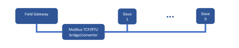
Slave addressing
Station addressing is supported by appending the slave address and a colon, before the actual address.
Example:
If you want to access holding register 40004 in a Modbus slave with the slave address nine, the address should be 9:40004.
Supported data types
The driver had been tested and supports the following data types
Digital signals
Bool – Single bit status, True or False
Analog signals
Int16 – 16 bit, single register value, with sign.
UInt16 – 16 bit, single register value, unsigned.
Int32 – 32 bit, two consecutive 16-bit registers, register value, with sign.
UInt32 – 32 bit, two consecutive 16-bit registers, unsigned.
Disclaimer
Please note that changes in the controller protocol or hardware, which may interfere with the functionality of this driver, may have occurred since this documentation was created. It is therefore important that you always test and verify the functionality of the application. To accommodate developments in the controller protocol and hardware, drivers are continuously updated. Accordingly, always ensure that the latest driver is used in the application.