Setting up an IIoT Gateway - Generation 4
This guide helps you setting up a gateway to use with the Connectitude IIoT Platform™.
Please read the reference guide for more in-depth details.
Connect to Internet - Using an ethernet connection
-
Connect an ethernet cable with Internet access to the cloud network on ethernet port 1 (ETH0).

-
Connect the necessary antennas (required for app configuration).
Connector Function 1 System status indicator LED 2 USB 3.0 connector 3 User programmable LED A & LED B 4 User programmable recessed push-button 6 System reset push-button 7 Console connector, micro-USB type 8 Antenna A, SMA 9 Industrial I/O terminal block, 16 pin, 16-26 AWG 10 Antenna B, SMA 11 Power input connector -
Power the IIoT Gateway using the supplied DC power input connector connected to a 12-24V PSU, or by using an appropriate PSU with 36W output supplying 12VDC 3A.
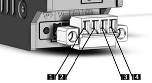
Pin Signal Name Description 1 +V V+ DC pin (for wire 16-20 AWG) 2 V- V0 DC pin (for wire 16-20 AWG) 3 CNTL Programmable power control 4 P.E. Protective Earth connection
Programmable power control
Connecting the remote power CNTL input to DC voltage may damage the device. Only connect the input pin to GND via contact switch.
Connect the machine network
-
Connect an ethernet cable with access to the LAN used for PLCs, for example, to the machine network on ethernet port 2 (ETH1).
