WISE-4050
This module is used for counting products
(frequency up to 3 kHz)
Plan the installation
This module needs to be connected to a 24V DC signal that goes high and low each time a product is produced.
Normally, the photocells and inductive sensors are wired back to a cabinet and PLC (check the wiring diagram for the machine).
A relay or output from the PLC works for some applications.
Wiring
Power the module from a 24V DC power source in the control cabinet (10-30 vdc)
+Vs - plus 24V DC
-Vs - minus 24V DC
Product counter
DI0 - plus 24V DC from the product counter signal (photocell, relay, etc.)
DI COM - minus 24V DC
Configuration
Initial Mode

- Set SW2-P1 to OFF before you power the module
- SW1-P1 & P2 = OFF (Counting 24V signals)
Wi-Fi connection
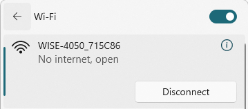
- Connect your computer to the hotspot network on the WISE-4050
Login
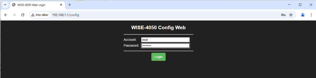
- Go to 192.168.1.1 using the web browser
Account: root
Password: 00000000
I/O Counter settings
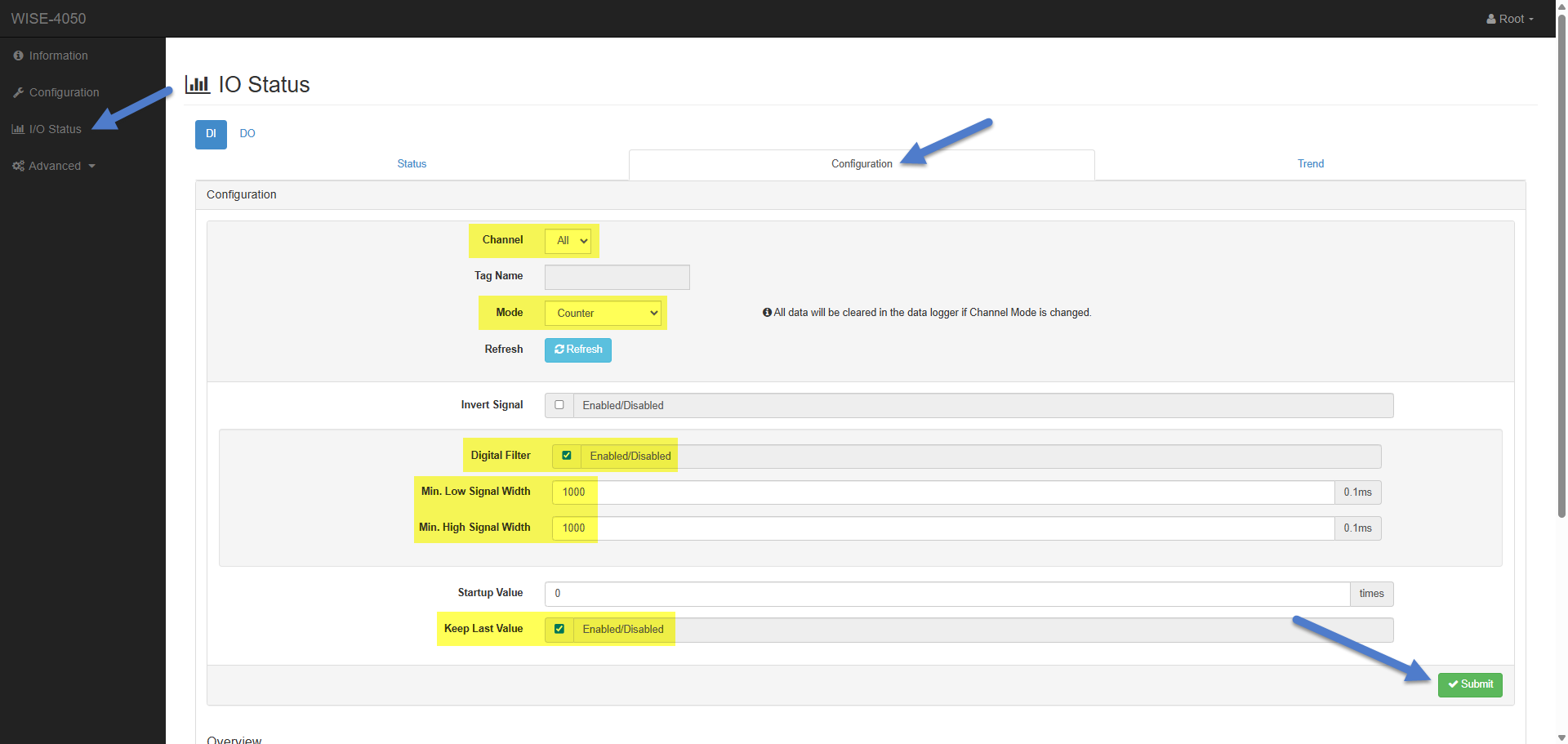
Navigate to I/O Status / Configuration
Channel = ALL
Mode = Counter
Digital Filter = Enable
Min. Low Signal Width = 1000
Max. Low Signal Width = 1000
Keep Last Value = Enable
If you have a fast-moving production, you might need to use a lower "Signal Width"
1000 = 100ms works fine when connected to a relay. If connected to a transistor, you don't need "Digital Filter".
Monitor counters
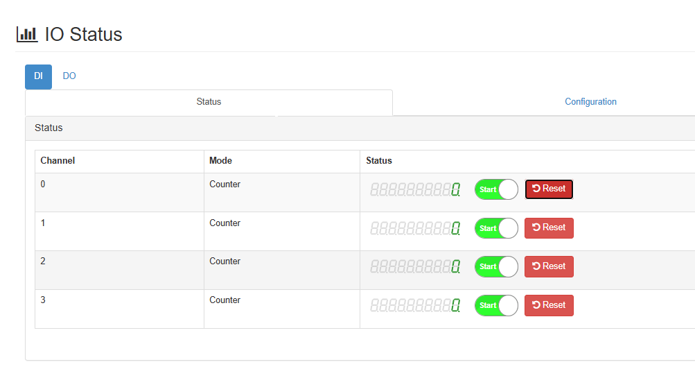
You can check the counters in this view
Wi-Fi settings
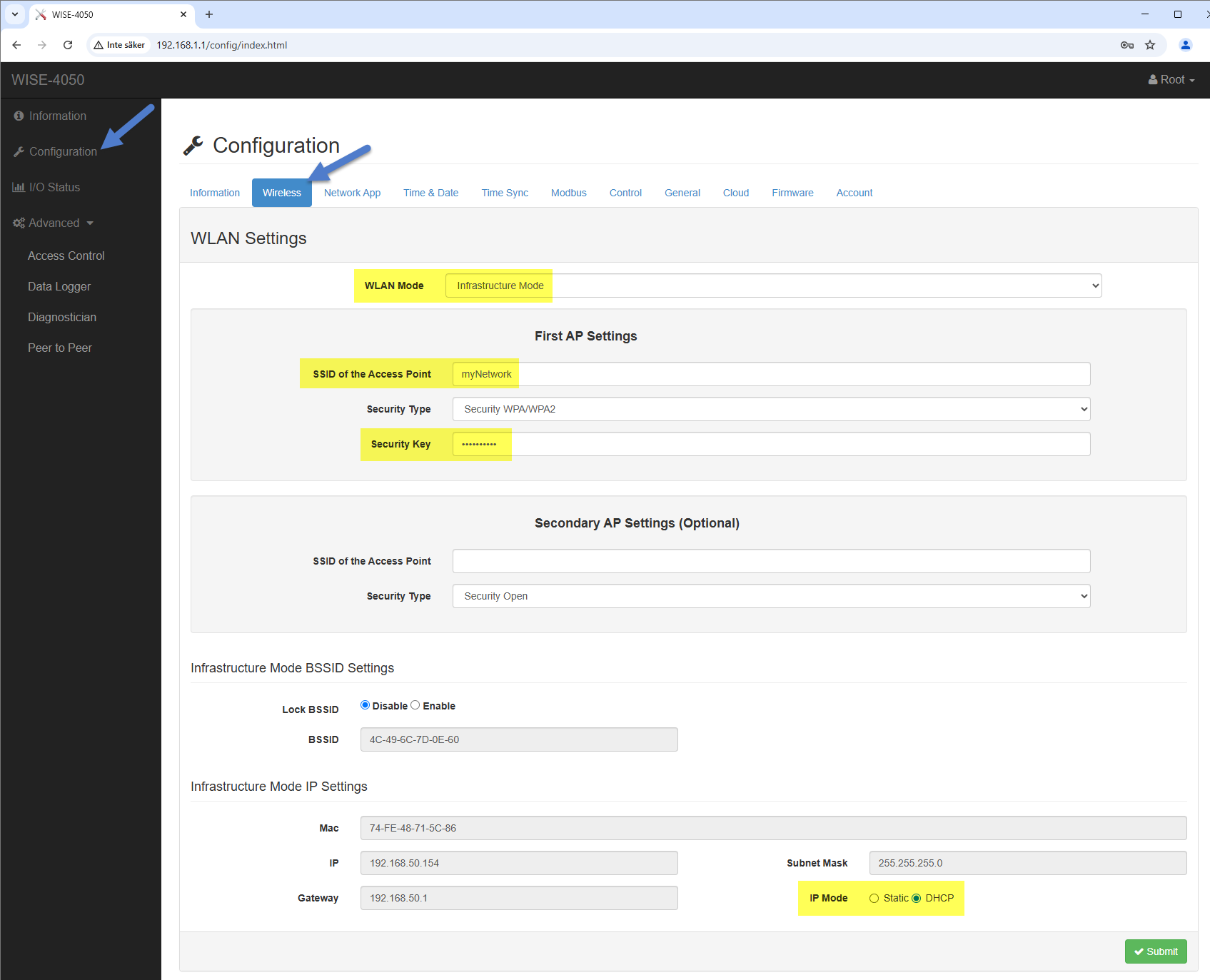
- Configuration/Wireless
- WLAN Mode = Infrastructure Mode
- SSID = network name
- Password = password
- IP Mode = DHCP
Normal Mode
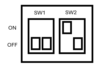
- Restore SW2-P1 to ON
- Restart the I/O module
Wi-Fi status
- Signal strength is shown with 4 LEDs
- If they are not on, check the SSID and password again
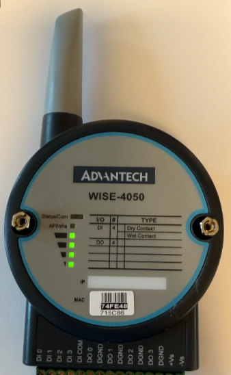
Find IP Address
- IT can find the IP address using the MAC address when connected to Wi-Fi
- You can also find this by setting the module to init mode again and logging in using the web interface
- Advanced IP Scanner can be used if you are on the same network
Reserve the IP address
- IT needs to reserve the IP address assigned by the DHCP server
Controller
Settings
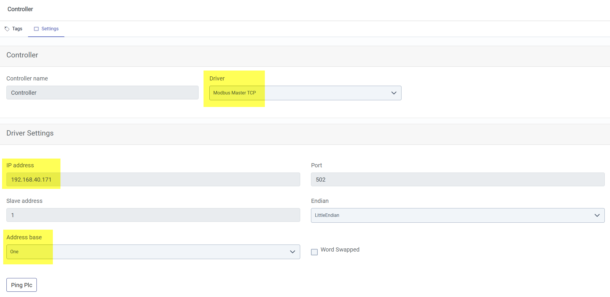
- IP address = xxx.xxx.xxx.xxx
- Address Base = One
Tags
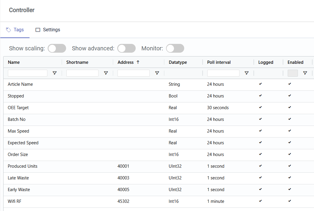
- Counter 1 (DI0) - Modbus Address: 40 001, Datatype: INT32
- Wi-Fi RF - Modbus Address: 45 302, Datatype: INT16
Manual reference guide